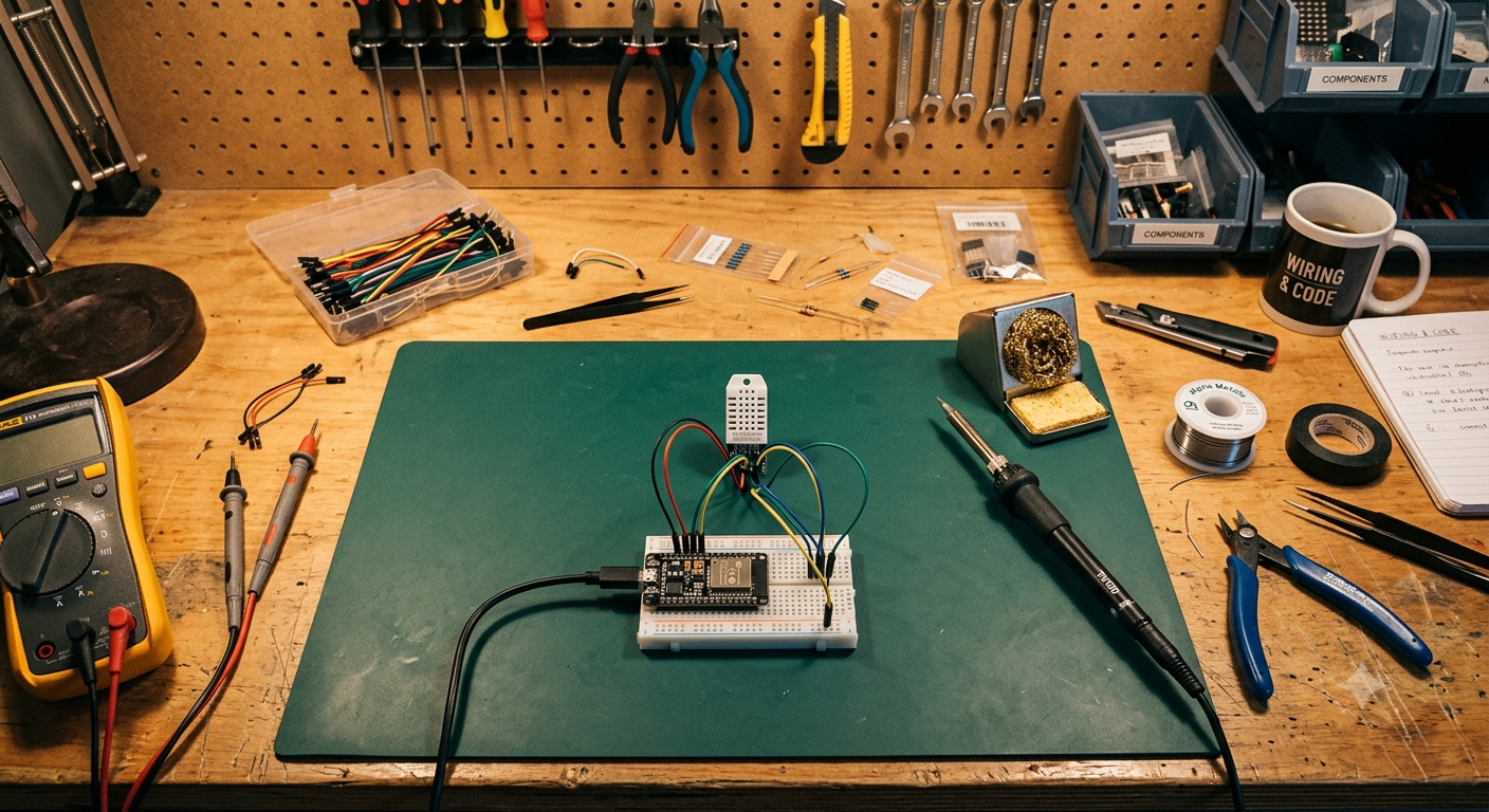
What You'll Build
This project reads the real temperature and humidity of a room, sends that data to a home automation system, and uses it to automatically turn a normal (non-smart) air conditioner on and off — no manual remote needed, no schedule guessing. If you've ever left the AC running in an empty room, or come home to a hot house because it wasn't running at all, this fixes that.
By the end of this guide you'll have:
- A small ESP32 device with a temperature/humidity sensor, connected to your Wi-Fi
- A 1.3" TFT display on the device itself, showing the live temperature and humidity
- A home automation system (Home Assistant) reading that data live
- An IR blaster that lets Home Assistant "press" your AC remote's buttons for you
- An automation that watches the temperature and turns the AC on or off accordingly
Parts List & Where to Buy
Everything here is easy to find on general electronics marketplaces (Amazon, AliExpress, or local electronics stores — in India, Robu.in and similar sites also stock all of these). Prices vary by region, so shop around.
| Part | What it's for |
|---|---|
| ESP32 Dev Board | The "brain" — a small Wi-Fi-capable microcontroller |
| DHT22 Sensor | Measures temperature and humidity |
| 1.3" TFT LCD Display (ST7789 driver) | Shows the live temperature and humidity on the device itself |
| Jumper wires (female-to-female, a handful) | Connects the sensor and display to the ESP32 without soldering |
| Micro-USB or USB-C cable | Powers the board and uploads firmware (check which port your board uses) |
| Wi-Fi IR Blaster (Tuya/SmartLife compatible) | Sends remote-control signals to your AC — explained fully below |
Part 1: Understanding the IR Blaster (Read This First)
Before wiring anything, it's worth understanding the two "black box" pieces of this project, because they're doing more work than they look like they are.
What is an IR blaster?
Almost every air conditioner remote — like almost every TV remote — talks to its appliance using infrared light, invisible to your eyes but readable by a small sensor on the AC unit. Every button press sends a unique pattern of infrared pulses.
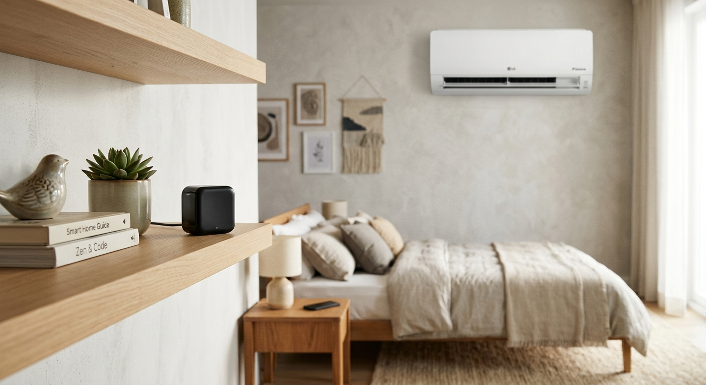
A Wi-Fi IR blaster is a small device — usually a plastic puck about the size of a hockey puck — that does two things:
- Learns your AC remote's IR signals by "listening" to them (you point your real remote at it and press a button, and it records the exact pattern)
- Replays those signals on command, over Wi-Fi, whenever your automation tells it to
In other words, it's a universal remote that a computer can control. It doesn't know anything about temperature or automation by itself — it just replays button presses when told to.
What is Tuya / SmartLife?
Tuya is a company that makes generic "smart home" hardware — plugs, bulbs, sensors, and IR blasters — which get sold under many different brand names. If you've ever bought a cheap smart plug from an unfamiliar brand, there's a good chance it's a Tuya device underneath.
SmartLife (and its close sibling, the "Tuya Smart" app) is the mobile app used to set up and control these devices. When you buy a Tuya-based IR blaster, this is the app you'll use first — you connect the blaster to your Wi-Fi through the app, then use the app to "teach" it your AC remote's signals by pointing the real remote at it.
Later, instead of controlling it through the SmartLife app by hand, Home Assistant connects to your Tuya account and can trigger those same learned signals automatically — that's the bridge that makes automation possible.
Setting up the IR blaster, step by step
- Download the SmartLife app (or "Tuya Smart") from your phone's app store
- Create an account and add the IR blaster device following the app's pairing instructions (usually holding a button until an LED blinks, then connecting via the app)
- Once connected, use the app's "Add Remote" or "Air Conditioner" feature — it will ask you to point your real AC remote at the blaster and press specific buttons (like Power) so it can learn the signal
- Test it directly in the app first — tap the on-screen power button and confirm the AC responds — before moving on to Home Assistant
- Place the blaster somewhere with a clear line of sight to the AC's IR receiver (usually a small dark window on the front of the unit) — the same way you'd need line of sight when using the physical remote
Part 2: Wiring the Temperature Sensor
The DHT22 sensor connects to the ESP32 with just three wires — no resistors or extra components needed for most breakout boards.
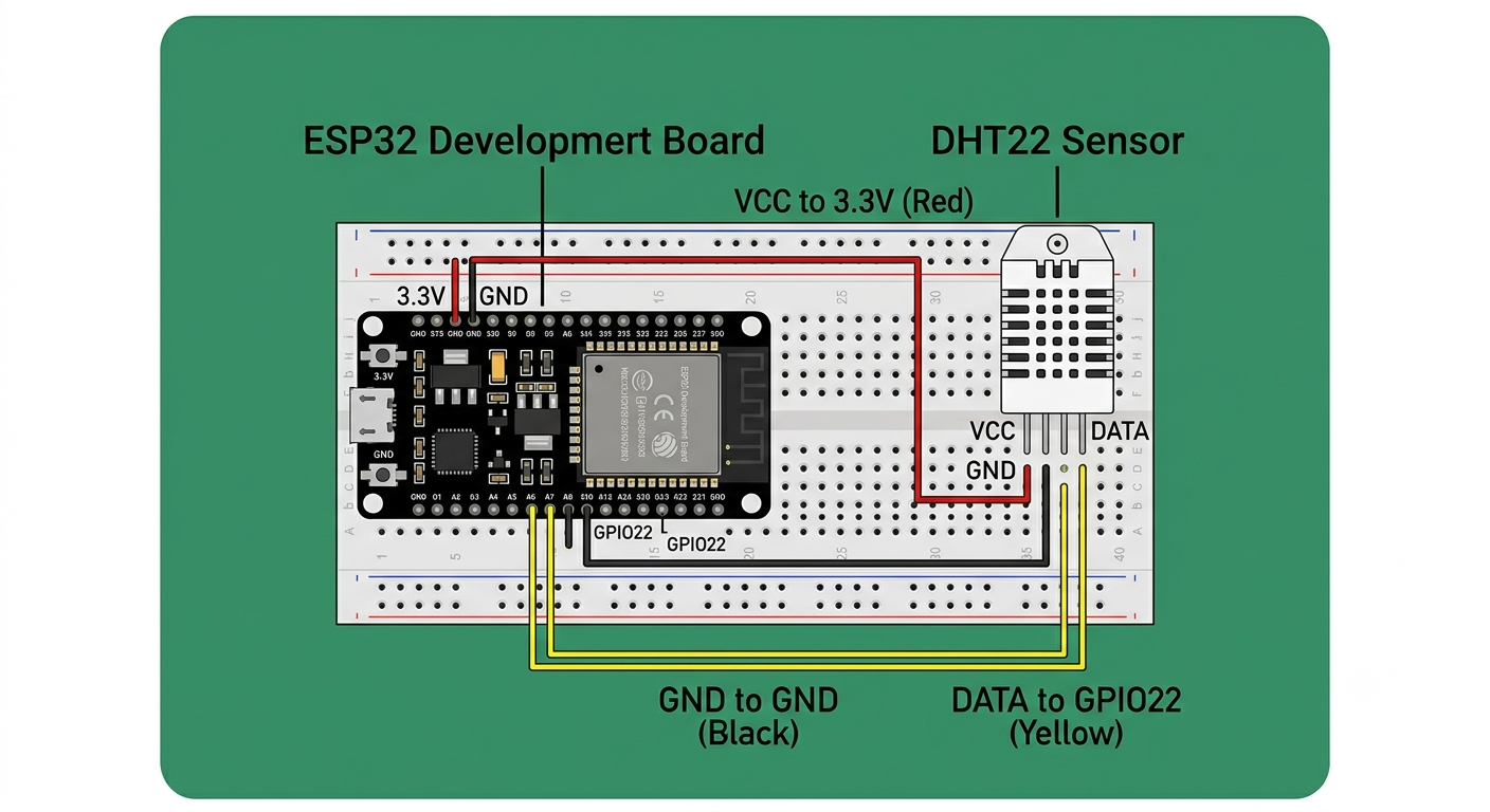
| DHT22 Pin | Connects to (ESP32) |
|---|---|
| VCC | 3.3V |
| GND | GND |
| DATA | GPIO22 |
If your DHT22 module is a bare 4-pin sensor (not a breakout board), you'll also need a 4.7kΩ–10kΩ resistor between VCC and DATA. Most breakout boards (the small blue PCBs the sensor is often mounted on) already include this resistor, so check yours before adding one.
Part 3: Wiring the Display
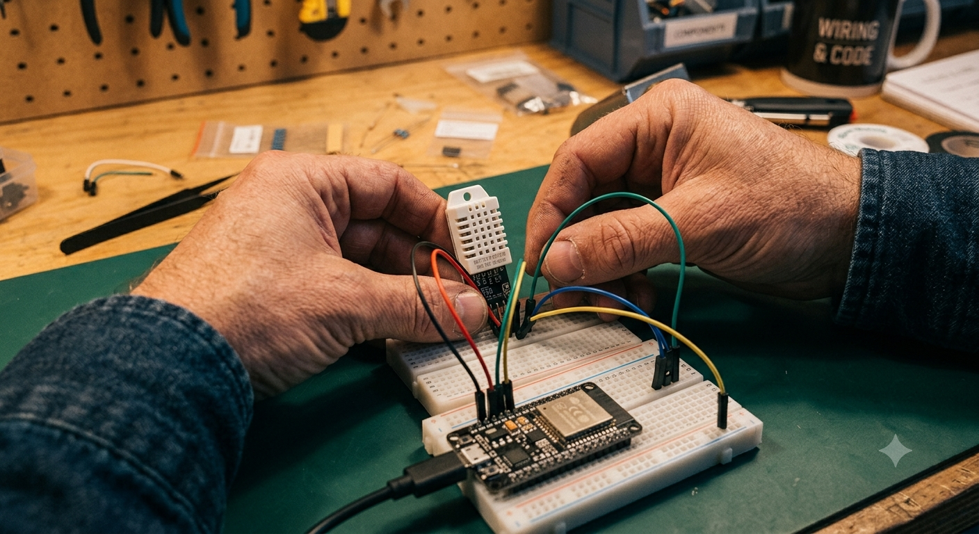
This build uses the same 1.3" TFT LCD (ST7789 driver) as the ESP32 voice assistant project — a small, sharp color display that talks to the ESP32 over SPI. It shows the live temperature and humidity right on the device, so you don't need to open Home Assistant just to check the room.
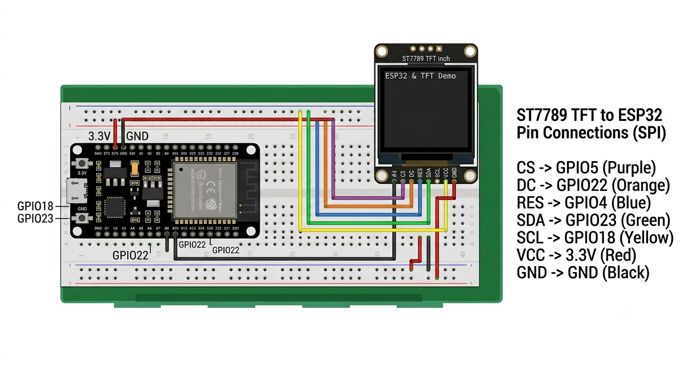
| Display Pin | Connects to (ESP32) |
|---|---|
| VCC | 3.3V |
| GND | GND |
| SCL / SCK (clock) | GPIO18 |
| SDA / MOSI (data) | GPIO23 |
| RES / RST (reset) | GPIO4 |
| DC (data/command) | GPIO2 |
| CS (chip select) | GPIO5 |
| BLK (backlight) | 3.3V, or a GPIO if you want to control brightness/on-off in software |
These pin numbers match the wiring used in the ESP32 voice assistant project — if your display module labels pins slightly differently (some boards swap SDA/SDI naming, for instance), match by function rather than by label name.
Add the display to your ESPHome configuration alongside the sensor, along with a time source so the display can show a live clock:
time:
  - platform: sntp
    id: my_time
    timezone: "Asia/Kolkata"

spi:
  clk_pin: GPIO18
  mosi_pin: GPIO23

display:
  - platform: st7789v
    model: "TTGO TDisplay 135x240"
    cs_pin: GPIO5
    dc_pin: GPIO2
    reset_pin: GPIO4
    rotation: 0
    lambda: |-
      it.strftime(0, 0, id(clock_font), "%H:%M:%S", id(my_time).now());
      it.print(0, 40, id(my_font), "Temp:");
      it.printf(0, 60, id(my_font), "%.1f C", id(bedroom_temp).state);
      it.print(0, 90, id(my_font), "Humidity:");
      it.printf(0, 110, id(my_font), "%.1f %%", id(bedroom_humidity).state);

font:
  - file: "gfonts://Roboto"
    id: my_font
    size: 20
  - file: "gfonts://Roboto"
    id: clock_font
    size: 28
The sntp time platform syncs the clock automatically over the internet once the ESP32 connects to Wi-Fi — no Home Assistant connection needed for the clock specifically. Set timezone to your own region using the standard tz database name (e.g. Asia/Kolkata for India).
model line and resolution can vary. Check your display's datasheet or product listing, or reuse the working config from a previous ST7789 project if you have one, and adjust the resolution/rotation to match.
You'll also need to give the temperature and humidity sensors from Part 1 fixed IDs (e.g. id: bedroom_temp) so the display's lambda block above can reference their live values directly on the device, without needing Home Assistant to be involved at all.
Part 4: Flashing the ESP32
This build uses ESPHome, a tool that lets you describe your device in a simple text file instead of writing full code. It handles Wi-Fi, over-the-air updates, and Home Assistant integration automatically.
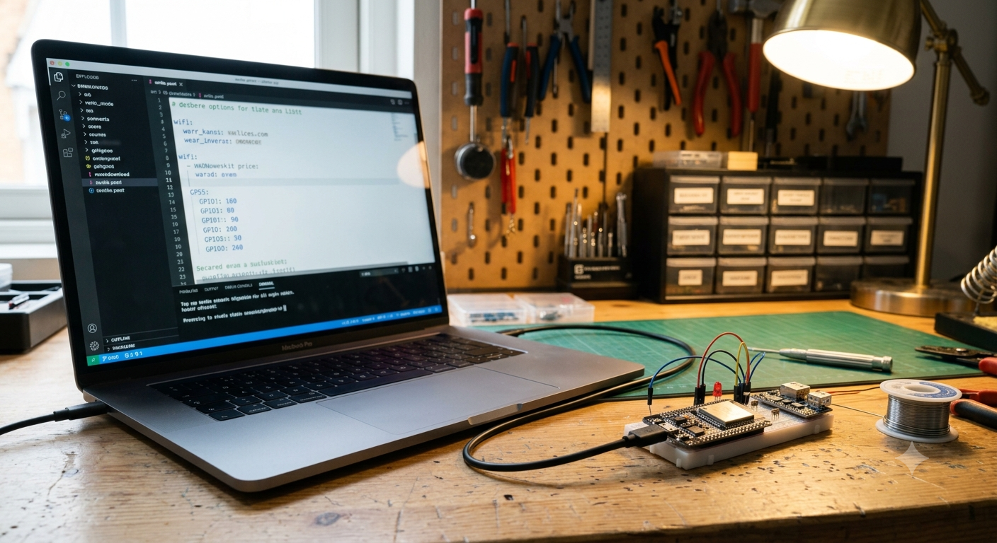
Install the ESPHome dashboard (it runs in your browser, or as a Home Assistant add-on if you're already running Home Assistant), then create a new device using this configuration:
esphome:
  name: bedroom-room-display

esp32:
  board: esp32dev
  framework:
    type: arduino

wifi:
  ssid: "YOUR_WIFI_NAME"
  password: "YOUR_WIFI_PASSWORD"

sensor:
  - platform: dht
    pin: GPIO22
    model: DHT22
    temperature:
      name: "Bedroom Room Display Room Temperature"
    humidity:
      name: "Bedroom Room Display Humidity"
    update_interval: 60s

api:
ota:YOUR_WIFI_NAME and YOUR_WIFI_PASSWORD are stand-ins so this guide doesn't show anyone's actual network. Just type your real Wi-Fi name and password directly in place of them on your own device.
Connect the ESP32 to your computer or phone via USB, select it in the ESPHome dashboard, and click Install. The first flash needs a cable; every update after that can be sent wirelessly (OTA).
Part 5: Connecting to Home Assistant
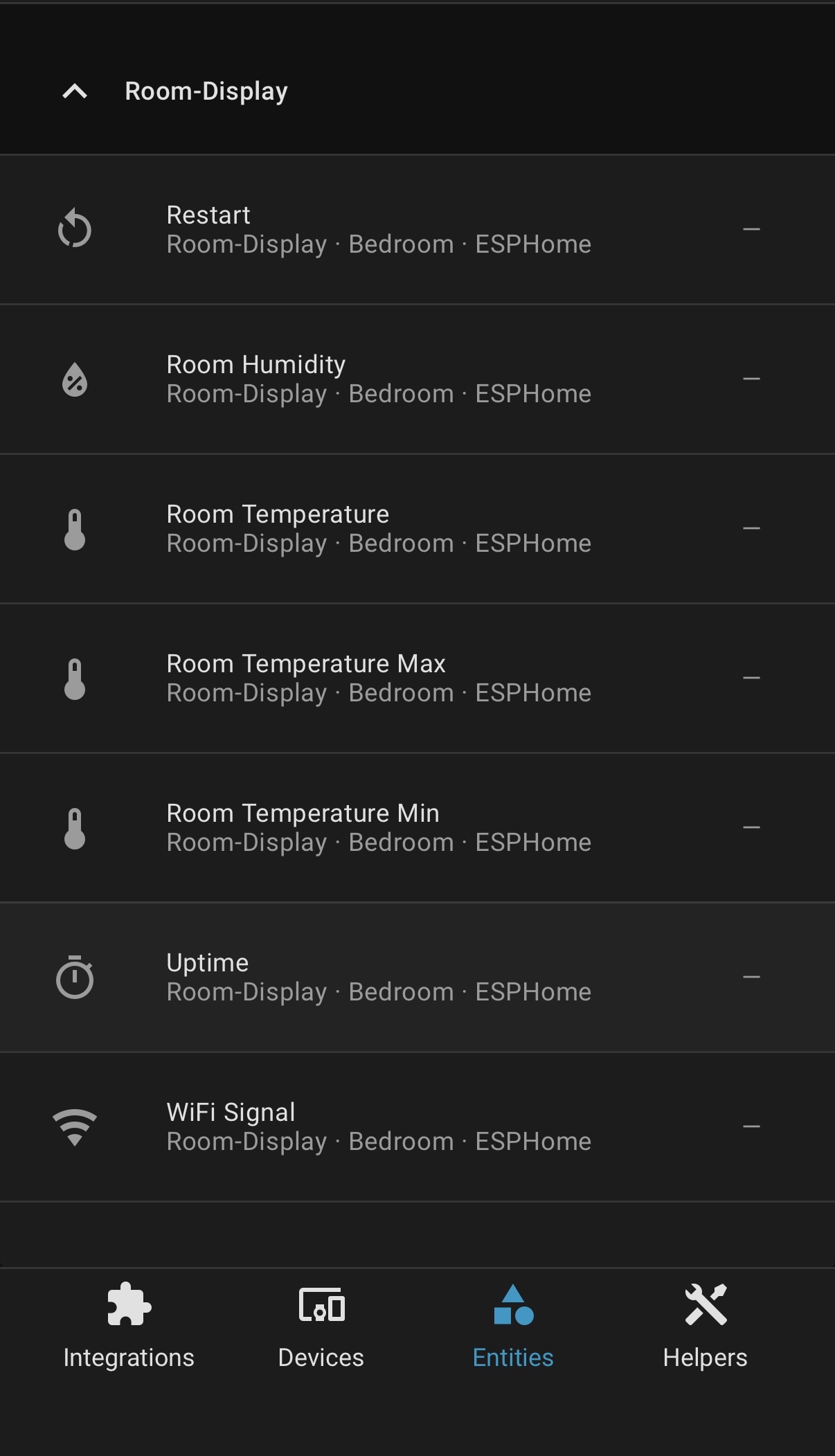
If you're running Home Assistant (see the full setup guide if you haven't installed it yet), the new ESP32 device should appear automatically as a discovered device (Settings → Devices & Services). Add it, and you'll get two live entities:
sensor.bedroom_room_display_room_temperaturesensor.bedroom_room_display_humidity
These update every 60 seconds and are now available to build automations from.
Separately, connect your Tuya/SmartLife account to Home Assistant through the Tuya integration (Settings → Devices & Services → Add Integration → Tuya). Once linked, the IR signals you learned earlier become "scenes" you can trigger from Home Assistant — in this build, they're named scene.air_on and scene.air_off.
Part 6: The Automation Logic
The simple version of this automation sounds easy: "turn on the AC when the temperature goes above 26°C." But a naive version of that rule has a real flaw.
Home Assistant's temperature-based triggers are edge-triggered — they only fire at the exact moment the temperature crosses the threshold. If Home Assistant restarts, or briefly loses connection right when that crossing happens, the automation can miss it entirely — and the AC gets stuck in the wrong state with nothing to correct it.
The fix is to add a second, time-based trigger that re-checks the condition every few minutes, so the system corrects itself even if it missed the original moment:
automation:
  - alias: "AC Auto Control"
    trigger:
      - platform: numeric_state
        entity_id: sensor.bedroom_room_display_room_temperature
        above: 26
      - platform: time_pattern
        minutes: "/5"
    condition:
      - condition: numeric_state
        entity_id: sensor.bedroom_room_display_room_temperature
        above: 26
      - condition: state
        entity_id: input_boolean.ac_should_be_on
        state: "off"
    action:
      - service: scene.turn_on
        target:
          entity_id: scene.air_on
      - service: input_boolean.turn_on
        target:
          entity_id: input_boolean.ac_should_be_on
A mirrored automation handles turning the AC off once the temperature drops back down. The input_boolean.ac_should_be_on helper matters more than it looks — IR blasters are one-way devices, so Home Assistant has no way to ask the AC "are you actually on right now?" This helper is Home Assistant's own memory of what it last told the AC to do, and the automation relies on it to avoid sending redundant or conflicting signals.
Part 7: Living With It — and Simplifying Later If You Want
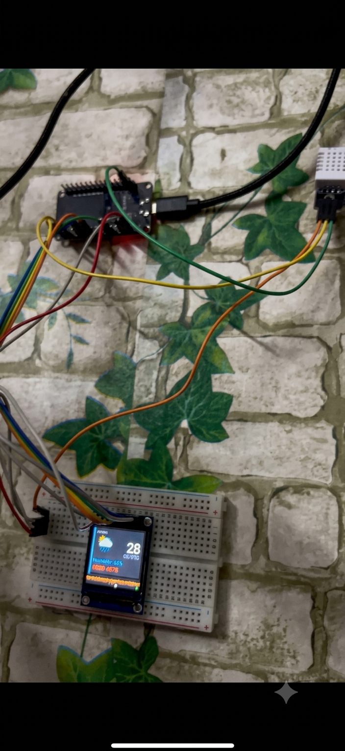
With the display wired up and the automation running, you get both: a live readout on the device itself, and a fully hands-off AC. In practice, once the automation has proven itself reliable, the on-device number becomes less necessary day-to-day — Home Assistant is already making the decisions, and the display is mostly a nice-to-have for a glance-and-check.
That's exactly what happened with this build over time: after the automation was trusted, the physical display was removed and the firmware simplified back down to sensor-only. This isn't a required step — it's just worth knowing it's a reasonable option later, rather than something you have to decide now. Build it with the display first; simplify only if you find you want to.
Troubleshooting
AC turns on or off at the wrong time after a restart. This is the edge-trigger issue from Part 5 — make sure the time-based secondary trigger is included.
Sensor shows "unavailable" in Home Assistant. Usually a loose DATA wire or a Wi-Fi drop. Check the ESPHome logs first — DHT22 sensors are sensitive to shaky jumper connections.
IR signal isn't reaching the AC. Reposition the blaster for a clearer, more direct line of sight to the AC's receiver window. A reflective wall behind the AC can sometimes help bounce the signal if a direct line isn't possible.